Our review to present the electric actuators’ range developed by FAIST for the regulation of turbocharger systems will be concluded with this article. On this occasion, we interviewed Tina Cortese, our Chief Product Innovation Officer of the CPS division, who answered a few questions about variable geometry compressors and introduced us to the latest entry in the Rotary Electric Actuators (REAs) range, the VC-REA.
Why did OEMs introduce systems with variable geometry compressors?
For decades technological developments in the internal combustion engine field aimed at maximizing performances and efficiency, and the protagonist of many innovations to that end has been the turbocharging system. With the increasingly stringent emissions limits in combustion processes, also the technologies applied to the turbocharger have become more advanced and complex. So far, the best results have been achieved working on the turbine side, which means maximizing the recovery of energy from the cylinders discharge flow, which lead to the diffusion of the turbine variable geometry, already covered in the article presenting our specific actuator for this application, the VT-REA.
As of today, instead, the developments on the compressor side have been focused on optimizing the geometry of the flow, but collided with the limits of the compressor’s optimal operational interval, which was not able to cover a wide-enough range of functional regimes of a specific engine. That means: you can either settle for working with a high performance of the compressor in a limited range of engine regimes, or opt for solutions that are more complex. The ones that are currently more widespread are systems composed by two turbocharger groups optimized to supply, in series or in parallel, high performances in a wider range of regimes.
These are nevertheless expensive solutions, and could not be ideal for those cases in which the measures adopted to reduce fuel consumption and therefore emissions of an internal combustion engine consist in a reduction of the vehicle’s weight.
In the end, it is the need to find a different way to guarantee a good compression efficiency that pushed many OEMs in the direction, trying to define a method to adapt the performance curve of the compressor itself, according to the need of the engine.
Can you describe us the working principles of turbocharging systems with variable geometry compressors?
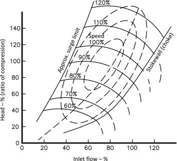
The aim is to broaden the high-efficiency operational range, and to extend the working interval of the compressor to those regimes where, in normal conditions and with a simple centrifugal compressor, the onset of instability phenomena is very likely. Looking at a generic compressor operational map, at low flow rates surge instability phenomena can happen, while at high rates the instability is linked to choking, when the compressor reaches sonic conditions in its most narrow part.
By dimensioning the compressor in such a way that choking is avoided at high ranges, the problem becomes how to prevent surge phenomena at low regimes. This phenomenon happens when the speed of the airflow coming into the compressor is so low, that the motion quantity in the fluid (its kinetic energy) is not sufficient to compensate the loss of energy associated with friction, and a positive gradient of pressure will be generated, contrasting the advancement of the fluid, and generating its detachment from the profile of the rotor blade.
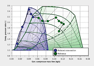
To solve the problem moving the stall limit, the compressor’s inlet section can be reduced, so that the speed of the flow entering the system is higher, being equal the flow rate (which means equal engine’s regime).
Basically, in the following picture (source: FVV), the green curve represents the efficiency map of a compressor optimized for high engine’s regimes. Reducing by 50% the inlet section area to the centrifugal compressor, we can obtain the compressor with the blue map, where the stall condition is moved to much lower regimes.
To get this flow rate restriction our clients developed different solutions, which all have in common the use of an actuator that is able to move the cinematic from an extreme to another position.
What type of turbocharger would this system cover for?
In many applications where currently twin- or bi-turbos are used (that is two turbocharging groups in series or in parallel), these can be substituted by a sole turbocharger with a variable geometry both on the turbine and on the compressor side. That would mean avoiding the need of an additional turbocharging system, with its controls and a good part of the by-pass system connecting the two groups.
In which engines could this solution be fitted?
By now, the applications we worked on while developing the actuator go from a 1.5L to a 2L gasoline engine. No impediment to the application on different engine displacements, but the interest of our clients is now on the high-volume platforms, where a reduction in cost and an increase in performances, associated with the cut of emissions, applied to high numbers, repay the investment of developing such a new technology.
What would be the advantage of fitting such a system on an engine for a client of FAIST?
As I previously stated, a reduction in weight and a smaller packaging wherever the bi-turbo, similar in performance, is replaced; obviously with this comes a reduction in the cost of the turbo system.
And which could be the potential disadvantages?
From a purely technical point of view, there are no real disadvantages. Generally speaking, one can consider a disadvantage to substitute a known technology with a new one, but the pros fully compensate this aspect. Getting in the details of the single projects, whenever we need to apply this solution on very compact and small engines, we need to find a way to fit an additional actuator very close to the compressor, or in the immediate surroundings of its intake pipe, but the compact packaging of the actuator we developed is suitable also for this kind of installation.
On which operating principles is FAIST’s VC-REA based?
The VC actuator developed by FAIST is a rotary actuator, which uses the torque provided by a small electric motor, and by a gears system designed to multiply this torque all the way to the actuation. The reduction group with its stages guarantees the torque levels requested by the application, generally lower compared to applications on the turbine side. To the mechanical part is associated a retroactive control operated by the control unit which uses the positioning signal of the actuator, provided through contactless position sensor, available as analogical signal, Sent or PWM.
What would you consider the highlights of this product?
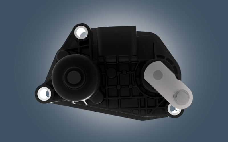
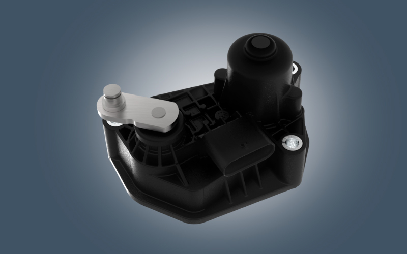
FAIST’s VC actuator is made of plastics, and is therefore light and compact, in a shape designed to adapt itself with minimal hindrance to the installation on the compressor volute.
The selection of the materials used for the external body was based on our experience on actuators for turbine applications: that is why we decided to use plastics that can resist in environments with a temperature range that goes from -40° C to 180°C.
Also for the gears, the experience done developing our more mature actuators (VT-REA and WG-REA) helped us in creating a reduction group able to resist to strain and wear for the entire life of the product.
Analogously the motor, as small and compact in dimensions, was selected and optimized in a way that minimizes wear.
What guided our development efforts were basically our customers’ requests: they provided us information regarding the specifications of resistance to endurance or wear cycles, thermal tests, vibration levels and environmental (electromagnetic) compatibility. All this data have been gathered in an organic design process, whose foundation was a careful analysis of the failure modes, with the aim of preventing them developing our VC-REA in a focused manner.
The actuator is obviously flexible in its ability to respond to the customer’s needs, both in terms of electrical interface (connector and pin-out) and regarding the fixing point, realized with pass-through holes reinforced with metallic bushings.
What is the current state of progress of the projects?
We finished the modeling and simulation of the concept design, which has been concretized in the production of prototypes who gave us the first confirmations in the preliminary tests phase. Now we are approaching the concept validation, from which we expect, besides many satisfactions, also useful causes for reflection and improvement.
Keep up the good work, FAIST’s R&D team!